IOS繪圖探索
Core Graphics Framework是一套基於C的API框架,使用了Quartz作為繪圖引擎。它提供了低級別、輕量級、高保真度的2D渲染。該框架可以用於基於路徑的繪圖、變換、顏色管理、脫屏渲染,模板、漸變、遮蔽、圖像數據管理、圖像的創建、遮罩以及PDF文檔的創建、顯示和分析。為了從感官上對這些概念做一個入門的認識,你可以運行一下官方的example code。
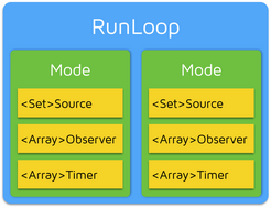
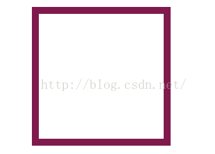
iOS支持兩套圖形API族:Core Graphics/QuartZ 2D 和OpenGL ES。 OpenGL ES是跨平台的圖形API,屬於OpenGL的一個簡化版本。 QuartZ 2D是蘋果公司開發的一套API,它是Core Graphics Framework的一部分。需要注意的是:OpenGL ES是應用程序編程接口,該接口描述了方法、結構、函數應具有的行為以及應該如何被使用的語義。也就是說它只定義了一套規范,具體的實現由設備制造商根據規范去做。而往往很多人對接口和實現存在誤解。舉一個不恰當的比喻:上發條的時鐘和裝電池的時鐘都有相同的可視行為,但兩者的內部實現截然不同。因為制造商可以自由的實現Open GL ES,所以不同系統實現的OpenGL ES也存在著巨大的性能差異。 Core Graphics API所有的操作都在一個上下文中進行。所以在繪圖之前需要獲取該上下文並傳入執行渲染的函數中。如果你正在渲染一副在內存中的圖片,此時就需要傳入圖片所屬的上下文。獲得一個圖形上下文是我們完成繪圖任務的第一步,你可以將圖形上下文理解為一塊畫布。如果你沒有得到這塊畫布,那麼你就無法完成任何繪圖操作。當然,有許多方式獲得一個圖形上下文,這裡我介紹兩種最為常用的獲取方法。 第一種方法就是創建一個圖片類型的上下文。調用UIGraphicsBeginImageContextWithOptions函數就可獲得用來處理圖片的圖形上下文。利用該上下文,你就可以在其上進行繪圖,並生成圖片。調用UIGraphicsGetImageFromCurrentImageContext函數可從當前上下文中獲取一個UIImage對象。記住在你所有的繪圖操作後別忘了調用UIGraphicsEndImageContext函數關閉圖形上下文。 第二種方法是利用cocoa為你生成的圖形上下文。當你子類化了一個UIView並實現了自己的drawRect:方法後,一旦drawRect:方法被調用,Cocoa就會為你創建一個圖形上下文,此時你對圖形上下文的所有繪圖操作都會顯示在UIView上。 判斷一個上下文是否為當前圖形上下文需要注意的幾點: 1.UIGraphicsBeginImageContextWithOptions函數不僅僅是創建了一個適用於圖形操作的上下文,並且該上下文也屬於當前上下文。 2.當drawRect方法被調用時,UIView的繪圖上下文屬於當前圖形上下文。 3.回調方法所持有的context:參數並不會讓任何上下文成為當前圖形上下文。此參數僅僅是對一個圖形上下文的引用罷了。 作為初學者,很容易被UIKit和Core Graphics兩個支持繪圖的框架迷惑。 UIKit 像UIImage、NSString(繪制文本)、UIBezierPath(繪制形狀)、UIColor都知道如何繪制自己。這些類提供了功能有限但使用方便的方法來讓我們完成繪圖任務。一般情況下,UIKit就是我們所需要的。 使用UiKit,你只能在當前上下文中繪圖,所以如果你當前處於UIGraphicsBeginImageContextWithOptions函數或drawRect:方法中,你就可以直接使用UIKit提供的方法進行繪圖。如果你持有一個context:參數,那麼使用UIKit提供的方法之前,必須將該上下文參數轉化為當前上下文。幸運的是,調用UIGraphicsPushContext 函數可以方便的將context:參數轉化為當前上下文,記住最後別忘了調用UIGraphicsPopContext函數恢復上下文環境。 Core Graphics 這是一個繪圖專用的API族,它經常被稱為QuartZ或QuartZ 2D。Core Graphics是iOS上所有繪圖功能的基石,包括UIKit。 使用Core Graphics之前需要指定一個用於繪圖的圖形上下文(CGContextRef),這個圖形上下文會在每個繪圖函數中都會被用到。如果你持有一個圖形上下文context:參數,那麼你等同於有了一個圖形上下文,這個上下文也許就是你需要用來繪圖的那個。如果你當前處於UIGraphicsBeginImageContextWithOptions函數或drawRect:方法中,並沒有引用一個上下文。為了使用Core Graphics,你可以調用UIGraphicsGetCurrentContext函數獲得當前的圖形上下文。 至此,我們有了兩大繪圖框架的支持以及三種獲得圖形上下文的方法(drawRect:、drawRect: inContext:、UIGraphicsBeginImageContextWithOptions)。那麼我們就有6種繪圖的形式。如果你有些困惑了,不用怕,我接下來將說明這6種情況。無需擔心還沒有具體的繪圖命令,你只需關注上下文如何被創建以及我們是在使用UIKit還是Core Graphics。 繪制邊框:
- (void)drawRect:(CGRect)rect
{
    CGContextRef context = UIGraphicsGetCurrentContext();
    CGMutablePathRef path = CGPathCreateMutable();

    CGPathAddRect(path, nil, rect);
    CGContextAddPath(context, path);
    //[[UIColor colorWithWhite:1.0f alpha:0.0f]setFill];
    [[UIColor colorWithRed:0.5 green:0.1 blue:0.3 alpha:1] setStroke];
    CGContextSetLineWidth(context, 20.f);
    CGContextDrawPath(context, kCGPathStroke);
    CGPathRelease(path);
}
運行結果:
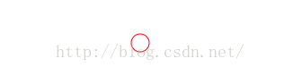
 繪制圓:
繪制圓:
- (void)drawRect:(CGRect)rect {

    CGContextRef content = UIGraphicsGetCurrentContext() ;
    //線的顏色
    UIColor* colorLine = [UIColor redColor] ;
    [colorLine setStroke];
    CGContextAddArc(content, rect.size.width/2, rect.size.height/2, 10, 0, 2*3.1415926, 0) ;
    CGContextStrokePath(content) ;
}
運行結果:
 CAShapeLayer和UIBazierPath繪制圓
#import "KACircleProgressView.h"
@interface KACircleProgressView : UIView {
    CAShapeLayer *_trackLayer;
    UIBezierPath *_trackPath;
    CAShapeLayer *_progressLayer;
    UIBezierPath *_progressPath;
}

@property (nonatomic, strong) UIColor *trackColor;
@property (nonatomic, strong) UIColor *progressColor;
@property (nonatomic) float progress;//0~1之間的數
@property (nonatomic) float progressWidth;

- (void)setProgress:(float)progress animated:(BOOL)animated;

@end
@implementation KACircleProgressView

- (id)initWithFrame:(CGRect)frame
{
    self = [super initWithFrame:frame];
    if (self) {
        // Initialization code
        _trackLayer = [CAShapeLayer new];
        [self.layer addSublayer:_trackLayer];
        _trackLayer.fillColor = nil;
        _trackLayer.frame = self.bounds;

        _progressLayer = [CAShapeLayer new];
        [self.layer addSublayer:_progressLayer];
        _progressLayer.fillColor = nil;
        _progressLayer.lineCap = kCALineCapRound;
        _progressLayer.frame = self.bounds;

        //默認5
        self.progressWidth = 5;
    }
    return self;
}

- (void)setTrack
{
    _trackPath = [UIBezierPath bezierPathWithArcCenter:self.center radius:(self.bounds.size.width - _progressWidth)/ 2 startAngle:0 endAngle:M_PI * 2 clockwise:YES];;
    _trackLayer.path = _trackPath.CGPath;
}

- (void)setProgress
{
    _progressPath = [UIBezierPath bezierPathWithArcCenter:self.center radius:(self.bounds.size.width - _progressWidth)/ 2 startAngle:- M_PI_2 endAngle:(M_PI * 2) * _progress - M_PI_2 clockwise:YES];
    _progressLayer.path = _progressPath.CGPath;
}


- (void)setProgressWidth:(float)progressWidth
{
    _progressWidth = progressWidth;
    _trackLayer.lineWidth = _progressWidth;
    _progressLayer.lineWidth = _progressWidth;

    [self setTrack];
    [self setProgress];
}

- (void)setTrackColor:(UIColor *)trackColor
{
    _trackLayer.strokeColor = trackColor.CGColor;
}

- (void)setProgressColor:(UIColor *)progressColor
{
    _progressLayer.strokeColor = progressColor.CGColor;
}

- (void)setProgress:(float)progress
{
    _progress = progress;

    [self setProgress];
}

- (void)setProgress:(float)progress animated:(BOOL)animated
{

}
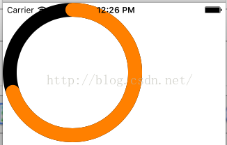
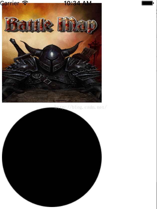
調用方式:
@implementation ViewController

- (void)viewDidLoad {
    KACircleProgressView *progress = [[KACircleProgressView alloc] initWithFrame:CGRectMake(0, 0, 200, 200)];
    [self.view addSubview:progress];
    progress.trackColor = [UIColor blackColor];
    progress.progressColor = [UIColor orangeColor];
    progress.progress = .7;
    progress.progressWidth = 20;
}
運行結果:
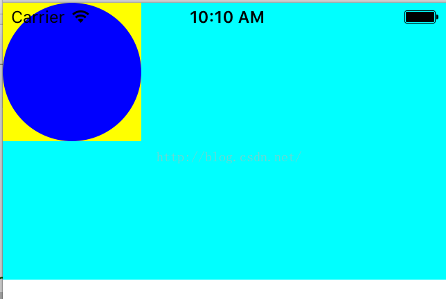
 以下在View 的drawRect方法中使用UIKit繪制矩形 和使用Core Graphics 在矩形中繪制圓
- (void)drawRect:(CGRect)rect {
    //繪制矩形
    UIBezierPath *bezierpath=[UIBezierPath bezierPathWithRect:CGRectMake(0, 0, 100, 100)];
    [[UIColor yellowColor] setFill];
    [bezierpath fill];

    //在矩形中繪制圓形
    CGContextRef con=UIGraphicsGetCurrentContext();
    CGContextAddEllipseInRect(con, CGRectMake(0, 0, 100, 100));
    CGContextSetFillColorWithColor(con, [UIColor blueColor].CGColor);
    CGContextFillPath(con);

}
運行結果
 在-(void)drawLayer:(CALayer *)layer inContext:(CGContextRef)cox 調用,同時寫了drawRect會將 drawRect的 UIGraphics操作給覆蓋掉
////這個方法實現會把drawRect 給屏蔽掉
-(void)drawLayer:(CALayer *)layer inContext:(CGContextRef)ctx
{
    UIGraphicsPushContext(ctx);

    UIBezierPath* p = [UIBezierPath bezierPathWithOvalInRect:CGRectMake(0,0,80,80)];

    [[UIColor groupTableViewBackgroundColor] setFill];

    [p fill];


}
以上兩個方法調用方式:
    cutomView*view=[[cutomView alloc]initWithFrame:CGRectMake(0, 0, 320, 200)];
    view.backgroundColor=[UIColor cyanColor];
    [self.view addSubview:view];

    cutomView* v=[[cutomView alloc]initWithFrame:CGRectMake(0, 220, 320, 200)];
    CALayer*l=[CALayer layer];
    l.cornerRadius=10;
    l.delegate=self;
    [v.layer addSublayer:l];
    [l setNeedsDisplay];
    [self.view addSubview:v];
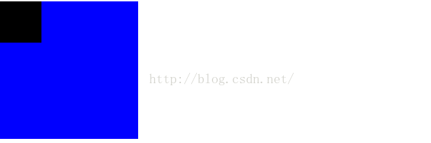
以下在View 的drawRect方法中使用Core Graphics 在矩形中擦除掉一個小方塊
- (void)drawRect:(CGRect)rect {
    self.backgroundColor=[UIColor whiteColor];
    CGContextRef con = UIGraphicsGetCurrentContext();

    CGContextSetFillColorWithColor(con, [UIColor blueColor].CGColor);

    CGContextFillRect(con, rect);

    CGContextClearRect(con, CGRectMake(0,0,30,30));
}
運行結果
將一張圖片轉換成一個圓形圖片.利用UIGraphicsEndImageContext
    UIImageView* imageView1=[[UIImageView alloc]initWithFrame:CGRectMake(10, 10, 200, 200)];
    UIImage* img=[UIImage imageNamed:@"a.png"];
    imageView1.image=img;
    [self.view addSubview:imageView1];

    UIImageView* imageView2=[[UIImageView alloc]initWithFrame:CGRectMake(10, 220, 200, 200)];
    UIImage* img2=[UIImage imageNamed:@"a.png"];

    UIGraphicsBeginImageContextWithOptions(CGSizeMake(100,100), NO, 0);
    UIBezierPath* p = [UIBezierPath bezierPathWithOvalInRect:CGRectMake(0,0,100,100)];

    [img2 drawAtPoint:CGPointMake(100, 0)];

    [p fill];

    UIImage* im = UIGraphicsGetImageFromCurrentImageContext();
    UIGraphicsEndImageContext();

    imageView2.image=im;
    [self.view addSubview:imageView2];
運行結果
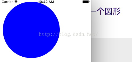
利用UIGraphicsBeginImageContextWithOptions和UIGraphicsGetCurrentContext繪制一個圓形
    UIGraphicsBeginImageContextWithOptions(CGSizeMake(100,100), NO, 0);

    CGContextRef con = UIGraphicsGetCurrentContext();

    CGContextAddEllipseInRect(con, CGRectMake(0,0,100,100));

    CGContextSetFillColorWithColor(con, [UIColor blueColor].CGColor);

    CGContextFillPath(con);

    UIImage* im = UIGraphicsGetImageFromCurrentImageContext();


    UIGraphicsEndImageContext();
    imageView1.image=im;


    [self.view addSubview:imageView1];
運行結果
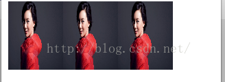
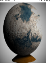
利用UIGraphicsBeginImageContextWithOptions平移三張圖片,三張圖片成為一張
    //平移三張
    UIImage* mars = [UIImage imageNamed:@"1.jpg"];

    CGSize sz = [mars size];

    UIGraphicsBeginImageContextWithOptions(CGSizeMake(sz.width*3, sz.height), NO, 0);

    [mars drawAtPoint:CGPointMake(0,0)];

    [mars drawAtPoint:CGPointMake(sz.width,0)];
    [mars drawAtPoint:CGPointMake(sz.width*2, 0)];

    UIImage* im3 = UIGraphicsGetImageFromCurrentImageContext();

    UIGraphicsEndImageContext();

    UIImageView* iv = [[UIImageView alloc] initWithImage:im3];

    iv.frame=CGRectMake(10, 20, 240, 100);
    [self.view addSubview:iv];
運行結果
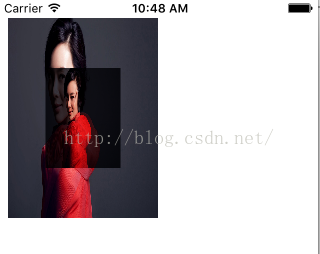
在一張大圖片獲得一張小圖片
 UIImage* mars = [UIImage imageNamed:@"1.jpg"];

    CGSize sz = [mars size];

    UIGraphicsBeginImageContextWithOptions(CGSizeMake(sz.width*2, sz.height*2), NO, 0);

    [mars drawInRect:CGRectMake(0,0,sz.width*2,sz.height*2)];

    [mars drawInRect:CGRectMake(sz.width/2.0, sz.height/2.0, sz.width, sz.height) blendMode:kCGBlendModeMultiply alpha:1.0];

    UIImage* im_suofang = UIGraphicsGetImageFromCurrentImageContext();

    UIGraphicsEndImageContext();

    UIImageView* iv = [[UIImageView alloc] initWithImage:im_suofang];

    iv.frame=CGRectMake(10, 20, 150, 200);
    [self.view addSubview:iv];
運行結果
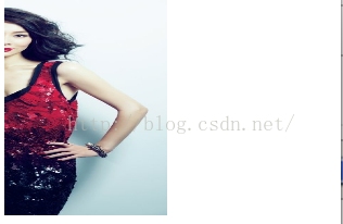
獲得一張圖片的右半邊
 //獲得圖片的右半邊

    UIImage* mars = [UIImage imageNamed:@"10.jpg"];

    CGSize sz = [mars size];

    UIGraphicsBeginImageContextWithOptions(CGSizeMake(sz.width/2.0, sz.height), NO, 0);

    [mars drawAtPoint:CGPointMake(-sz.width/2.0, 0)];

    UIImage* im_right = UIGraphicsGetImageFromCurrentImageContext();

    UIGraphicsEndImageContext();

    UIImageView* iv = [[UIImageView alloc] initWithImage:im_right];

    iv.frame=CGRectMake(10, 20, 150, 200);
    [self.view addSubview:iv];
運行結果:
將圖片分開拆成兩張圖片,分別繪制在上下文的左右兩邊
 //下面的代碼展示了將圖片拆分成兩半,並分別繪制在上下文的左右兩邊:
    UIImage* mars = [UIImage imageNamed:@"33.jpg"];
    UIImageView* iv1 = [[UIImageView alloc] initWithImage:mars];

    iv1.frame=CGRectMake(10, 20, 150, 200);
    [self.view addSubview:iv1];


    // 抽取圖片的左右半邊

    CGSize sz = [mars size];

    CGImageRef marsLeft = CGImageCreateWithImageInRect([mars CGImage],CGRectMake(0,0,sz.width/2.0,sz.height));

    CGImageRef marsRight = CGImageCreateWithImageInRect([mars CGImage],CGRectMake(sz.width/2.0,0,sz.width/2.0,sz.height));

    // 將每一個CGImage繪制到圖形上下文中

    UIGraphicsBeginImageContextWithOptions(CGSizeMake(sz.width*1.5, sz.height), NO, 0);

    CGContextRef con1 = UIGraphicsGetCurrentContext();

    CGContextDrawImage(con1, CGRectMake(0,0,sz.width/2.0,sz.height), marsLeft);

    CGContextDrawImage(con1, CGRectMake(sz.width,0,sz.width/2.0,sz.height), marsRight);

    UIImage* im_both = UIGraphicsGetImageFromCurrentImageContext();

    UIGraphicsEndImageContext();

    // 記得釋放內存,ARC在這裡無效

    CGImageRelease(marsLeft);

    CGImageRelease(marsRight);

    UIImageView* iv = [[UIImageView alloc] initWithImage:im_both];

    iv.frame=CGRectMake(10, 240, 150, 200);
    [self.view addSubview:iv];
運行結果,不要YY哦
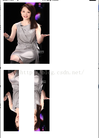
你也許發現繪出的圖是上下顛倒的!圖片的顛倒並不是因為被旋轉了。當你創建了一個CGImage並使用CGContextDrawImage方法繪圖就會引起這種問題。這主要是因為原始的本地坐標系統(坐標原點在左上角)與目標上下文(坐標原點在左下角)不匹配
以下為修正方案
    //下面的代碼展示了將圖片拆分成兩半,並分別繪制在上下文的左右兩邊:
    UIImage* mars = [UIImage imageNamed:@"33.jpg"];

    // 抽取圖片的左右半邊

    CGSize sz = [mars size];

    CGImageRef marsLeft = CGImageCreateWithImageInRect([mars CGImage],CGRectMake(0,0,sz.width/2.0,sz.height));

    CGImageRef marsRight = CGImageCreateWithImageInRect([mars CGImage],CGRectMake(sz.width/2.0,0,sz.width/2.0,sz.height));

    // 將每一個CGImage繪制到圖形上下文中

    UIGraphicsBeginImageContextWithOptions(CGSizeMake(sz.width*1.5, sz.height), NO, 0);

    CGContextRef con1 = UIGraphicsGetCurrentContext();

    CGContextDrawImage(con1, CGRectMake(0,0,sz.width/2.0,sz.height), flip(marsLeft));

    CGContextDrawImage(con1, CGRectMake(sz.width,0,sz.width/2.0,sz.height), flip(marsRight));

    UIImage* im1 = UIGraphicsGetImageFromCurrentImageContext();

    UIGraphicsEndImageContext();

    // 記得釋放內存,ARC在這裡無效

    CGImageRelease(marsLeft);

    CGImageRelease(marsRight);

    UIImageView* iv = [[UIImageView alloc] initWithImage:im1];

    iv.frame=CGRectMake(10, 20, 150, 200);
    [self.view addSubview:iv];
運行結果
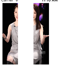
//在雙分辨率的設備上,如果我們的圖片文件是高分辨率(@2x)版本,上面的繪圖就是錯誤的。原因在於對於UIImage來說,在加載原始圖片時使用imageNamed:方法,它會自動根據所在設備的分辨率類型選擇圖片,並且UIImage通過設置用來適配的scale屬性補償圖片的兩倍尺寸。但是一個CGImage對象並沒有scale屬性,它不知道圖片文件的尺寸是否為兩倍!所以當調用UIImage的CGImage方法,你不能假定所獲得的CGImage尺寸與原始UIImage是一樣的。在單分辨率和雙分辨率下,一個UIImage對象的size屬性值都是一樣的,但是雙分辨率UIImage對應的CGImage是單分辨率UIImage對應的CGImage的兩倍大
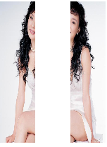
另外一種處理倒置問題
    //這裡還有另一種修復倒置問題的方案。相對於使用flip函數,你可以在繪圖之前將CGImage包裝進UIImage中,這樣做有兩大優點:
    //1.當UIImage繪圖時它會自動修復倒置問題
    //2.當你從CGImage轉化為Uimage時,可調用imageWithCGImage:scale:orientation:方法生成CGImage作為對縮放性的補償。

    UIImage* mars = [UIImage imageNamed:@"13.jpg"];

    CGSize sz = [mars size];

    CGImageRef marsCG = [mars CGImage];

    CGSize szCG = CGSizeMake(CGImageGetWidth(marsCG), CGImageGetHeight(marsCG));

    CGImageRef marsLeft = CGImageCreateWithImageInRect(marsCG, CGRectMake(0,0,szCG.width/2.0,szCG.height));

    CGImageRef marsRight = CGImageCreateWithImageInRect(marsCG, CGRectMake(szCG.width/2.0,0,szCG.width/2.0,szCG.height));

    UIGraphicsBeginImageContextWithOptions(CGSizeMake(sz.width*1.5, sz.height), NO, 0);

    [[UIImage imageWithCGImage:marsLeft scale:[mars scale] orientation:UIImageOrientationUp] drawAtPoint:CGPointMake(0,0)];

    [[UIImage imageWithCGImage:marsRight scale:[mars scale] orientation:UIImageOrientationUp] drawAtPoint:CGPointMake(sz.width,0)];

    UIImage* im1 = UIGraphicsGetImageFromCurrentImageContext();

    UIGraphicsEndImageContext();

    CGImageRelease(marsLeft); CGImageRelease(marsRight);

    UIImageView* iv = [[UIImageView alloc] initWithImage:im1];

    iv.frame=CGRectMake(10, 20, 150, 200);
    [self.view addSubview:iv];
CGImageRef flip (CGImageRef im) {

    CGSize sz = CGSizeMake(CGImageGetWidth(im), CGImageGetHeight(im));

    UIGraphicsBeginImageContextWithOptions(sz, NO, 0);

    CGContextDrawImage(UIGraphicsGetCurrentContext(), CGRectMake(0, 0, sz.width, sz.height), im);

    CGImageRef result = [UIGraphicsGetImageFromCurrentImageContext() CGImage];

    UIGraphicsEndImageContext();

    return result;

}
運行結果:
濾鏡
    UIImage* moi = [UIImage imageNamed:@"Mars.jpeg"];

    CIImage* moi2 = [[CIImage alloc] initWithCGImage:moi.CGImage];

    CIFilter* grad = [CIFilter filterWithName:@"CIRadialGradient"];

    CIVector* center = [CIVector vectorWithX:moi.size.width / 2.0 Y:moi.size.height / 2.0];

    // 使用setValue:forKey:方法設置濾鏡屬性

    [grad setValue:center forKey:@"inputCenter"];

    // 在指定濾鏡名時提供所有濾鏡鍵值對

    CIFilter* dark = [CIFilter filterWithName:@"CIDarkenBlendMode" keysAndValues:@"inputImage", grad.outputImage, @"inputBackgroundImage", moi2, nil];

    CIContext* c = [CIContext contextWithOptions:nil];

    CGImageRef moi3 = [c createCGImage:dark.outputImage fromRect:moi2.extent];

    UIImage* moi4 = [UIImage imageWithCGImage:moi3 scale:moi.scale orientation:moi.imageOrientation];

    CGImageRelease(moi3);

    UIImageView* iv1 = [[UIImageView alloc] initWithImage:moi4];

    iv1.frame=CGRectMake(10, 20, 150, 200);
    [self.view addSubview:iv1];
運行結果
以下是繪制箭頭的N種方法
#import "ArrowheadView.h"
@implementation ArrowheadView
// Only override drawRect: if you perform custom drawing.
// An empty implementation adversely affects performance during animation.
- (void)drawRect:(CGRect)rect {
CGContextRef con = UIGraphicsGetCurrentContext();
#if 0
// 繪制一個黑色的垂直黑色線,作為箭頭的桿子
CGContextMoveToPoint(con, 100, 100);
CGContextAddLineToPoint(con, 100, 19);
CGContextSetLineWidth(con, 20);
CGContextStrokePath(con);
// 繪制一個紅色三角形箭頭
CGContextSetFillColorWithColor(con, [[UIColor redColor] CGColor]);
CGContextMoveToPoint(con, 80, 25);
CGContextAddLineToPoint(con, 100, 0);
CGContextAddLineToPoint(con, 120, 25);
CGContextFillPath(con);
// 從箭頭桿子上裁掉一個三角形,使用清除混合模式
CGContextSaveGState(con);
{
CGContextSetFillColorWithColor(con, [[UIColor whiteColor] CGColor]);
CGContextMoveToPoint(con, 90, 101);
CGContextAddLineToPoint(con, 100, 90);
CGContextAddLineToPoint(con, 110, 101);
CGContextSetBlendMode(con, kCGBlendModeClear);
CGContextFillPath(con);
}
CGContextRestoreGState(con);
#endif
/**
* 如果一段路徑需要重用或共享,你可以將路徑封裝為CGPath(具體類型是CGPathRef)。你可以創建一個新的CGMutablePathRef對象並使用多個類似於圖形的路徑函數的CGPath函數構造路徑,或者使用CGContextCopyPath函數復制圖形上下文的當前路徑。有許多CGPath函數可用於創建基於簡單幾何形狀的路徑(CGPathCreateWithRect、CGPathCreateWithEllipseInRect)或基於已存在路徑(CGPathCreateCopyByStrokingPath、CGPathCreateCopyDashingPath、CGPathCreateCopyByTransformingPath)。
UIKit的UIBezierPath類包裝了CGPath。它提供了用於繪制某種形狀路徑的方法,以及用於描邊、填充、存取某些當前上下文狀態的設置方法。類似地,UIColor提供了用於設置當前上下文描邊與填充的顏色。因此我們可以重寫我們之前繪制箭頭的代碼
*/
#if 0
UIBezierPath* p = [UIBezierPath bezierPath];
[p moveToPoint:CGPointMake(100,100)];
[p addLineToPoint:CGPointMake(100, 19)];
[p setLineWidth:20];
[p stroke];
[[UIColor redColor] set];
[p removeAllPoints];
[p moveToPoint:CGPointMake(80,25)];
[p addLineToPoint:CGPointMake(100, 0)];
[p addLineToPoint:CGPointMake(120, 25)];
[p fill];
[p removeAllPoints];
[[UIColor clearColor] set];
[p moveToPoint:CGPointMake(90,101)];
[p addLineToPoint:CGPointMake(100, 90)];
[p addLineToPoint:CGPointMake(110, 101)];
[p fillWithBlendMode:kCGBlendModeClear alpha:1.0];
#endif
/**
* 完成同樣的工作並沒有節省多少代碼,但是UIBezierPath仍然還是有用的。如果你需要對象特性,UIBezierPath提供了一個便利方法:bezierPathWithRoundedRect:cornerRadius:,它可用於繪制帶有圓角的矩形,如果是使用Core Graphics就相當冗長乏味了。還可以只讓圓角出現在左上角和右上角。
*/
#if 0
CGContextRef ctx = UIGraphicsGetCurrentContext();
CGContextSetStrokeColorWithColor(ctx, [UIColor blackColor].CGColor);
CGContextSetLineWidth(ctx, 3);
UIBezierPath *path;
path = [UIBezierPath bezierPathWithRoundedRect:CGRectMake(0, 0, 100, 100) byRoundingCorners:(UIRectCornerTopLeft |UIRectCornerTopRight) cornerRadii:CGSizeMake(10, 10)];
[path stroke];
#endif
#if 0
/**
* 裁剪
路徑的另一用處是遮蔽區域,以防對遮蔽區域進一步繪圖。這種用法被稱為裁剪。裁剪區域外的圖形不會被繪制到。默認情況下,一個圖形上下文的裁剪區域是整個圖形上下文。你可在上下文中的任何地方繪圖。
總的來說,裁剪區域是上下文的一個特性。與已存在的裁剪區域相交會出現新的裁剪區域。所以如果你應用了你自己的裁剪區域,稍後將它從圖形上下文中移除的做法是使用CGContextSaveGState和CGContextRestoreGState函數將代碼包裝起來。
為了便於說明這一點,我使用裁剪而不是使用混合模式在箭頭桿子上打孔的方法重寫了生成箭頭的代碼。這樣做有點小復雜,因為我們想要裁剪區域不在三角形內而在三角形外部。為了表明這一點,我們使用了一個三角形和一個矩形組成了一個組合路徑。
當填充一個組合路徑並使用它表示一個裁剪區域時,系統遵循以下兩規則之一:
環繞規則(Winding rule)
如果邊界是順時針繪制,那麼在其內部逆時針繪制的邊界所包含的內容為空。如果邊界是逆時針繪制,那麼在其內部順時針繪制的邊界所包含的內容為空。
奇偶規則
最外層的邊界代表內部都有效,都要填充;之後向內第二個邊界代表它的內部無效,不需填充;如此規則繼續向內尋找邊界線。我們的情況非常簡單,所以使用奇偶規則就很容易了。這裡我們使用CGContextEOCllip設置裁剪區域然後進行繪圖
*/
// 在上下文裁剪區域中挖一個三角形狀的孔
CGContextMoveToPoint(con, 90, 100);
CGContextAddLineToPoint(con, 100, 90);
CGContextAddLineToPoint(con, 110, 100);
CGContextClosePath(con);
CGContextAddRect(con, CGContextGetClipBoundingBox(con));
// 使用奇偶規則,裁剪區域為矩形減去三角形區域
CGContextEOClip(con);
// 繪制垂線
CGContextMoveToPoint(con, 100, 100);
CGContextAddLineToPoint(con, 100, 19);
CGContextSetLineWidth(con, 20);
CGContextStrokePath(con);
// 畫紅色箭頭
CGContextSetFillColorWithColor(con, [[UIColor redColor] CGColor]);
CGContextMoveToPoint(con, 80, 25);
CGContextAddLineToPoint(con, 100, 0);
CGContextAddLineToPoint(con, 120, 25);
CGContextFillPath(con);
#endif
#if 0
/**
* 漸變
漸變可以很簡單也可以很復雜。一個簡單的漸變(接下來要討論的)由一端點的顏色與另一端點的顏色決定,如果在中間點加入顏色(可選),那麼漸變會在上下文的兩個點之間線性的繪制或在上下文的兩個圓之間放射狀的繪制。不能使用漸變作為路徑的填充色,但可使用裁剪限制對路徑形狀的漸變。
我重寫了繪制箭頭的代碼,箭桿使用了線性漸變
*/
CGContextSaveGState(con);
// 在上下文裁剪區域挖一個三角形孔
CGContextMoveToPoint(con, 90, 100);
CGContextAddLineToPoint(con, 100, 90);
CGContextAddLineToPoint(con, 110, 100);
CGContextClosePath(con);
CGContextAddRect(con, CGContextGetClipBoundingBox(con));
CGContextEOClip(con);
//繪制一個垂線,讓它的輪廓形狀成為裁剪區域
CGContextMoveToPoint(con, 100, 100);
CGContextAddLineToPoint(con, 100, 19);
CGContextSetLineWidth(con, 20);
// 使用路徑的描邊版本替換圖形上下文的路徑
CGContextReplacePathWithStrokedPath(con);
// 對路徑的描邊版本實施裁剪
CGContextClip(con);
// 繪制漸變
CGFloat locs[3] = { 0.0, 0.5, 1.0 };
CGFloat colors[12] = {
0.3,0.3,0.3,0.8, // 開始顏色,透明灰
0.0,0.0,0.0,1.0, // 中間顏色,黑色
0.3,0.3,0.3,0.8 // 末尾顏色,透明灰
};
CGColorSpaceRef sp = CGColorSpaceCreateDeviceGray();
CGGradientRef grad = CGGradientCreateWithColorComponents (sp, colors, locs, 3);
CGContextDrawLinearGradient(con, grad, CGPointMake(89,0), CGPointMake(111,0), 0);
CGColorSpaceRelease(sp);
CGGradientRelease(grad);
CGContextRestoreGState(con); // 完成裁剪
// 繪制紅色箭頭
CGContextSetFillColorWithColor(con, [[UIColor redColor] CGColor]);
CGContextMoveToPoint(con, 80, 25);
CGContextAddLineToPoint(con, 100, 0);
CGContextAddLineToPoint(con, 120, 25);
CGContextFillPath(con);
//調用CGContextReplacePathWithStrokedPath函數假裝對當前路徑描邊,並使用當前線段寬度和與線段相關的上下文狀態設置。但接著創建的是描邊路徑外部的一個新的路徑。因此,相對於使用粗的線條,我們使用了一個矩形區域作為裁剪區域。
//雖然過程比較冗長但是非常的簡單;我們將漸變描述為一組在一端點(0.0)和另一端點(1.0)之間連續區上的位置,以及設置與每個位置相對應的顏色。為了提亮邊緣的漸變,加深中間的漸變,我使用了三個位置,黑色點的位置是0.5。為了創建漸變,還需要提供一個顏色空間。最後,我創建出了該漸變,並對裁剪區域繪制線性漸變,最後釋放了顏色空間和漸變。
#endif
#if 0
/**
* 顏色與模板
在iOS中,CGColor表示顏色(具體類型為CGColorRef)。使用UIColor的colorWithCGColor:和CGColor方法可bridged cast到UIColor。
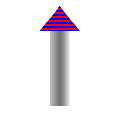
在iOS中,模板表示為CGPattern(具體類型為CGPatternRef)。你可以創建一個模板並使用它進行描邊或填充。其過程是相當復雜的。作為一個非常簡單的例子,我將使用紅藍相間的三角形替換箭頭的三
*/
CGContextSaveGState(con);
// 在上下文裁剪區域挖一個三角形孔
CGContextMoveToPoint(con, 90, 100);
CGContextAddLineToPoint(con, 100, 90);
CGContextAddLineToPoint(con, 110, 100);
CGContextClosePath(con);
CGContextAddRect(con, CGContextGetClipBoundingBox(con));
CGContextEOClip(con);
//繪制一個垂線,讓它的輪廓形狀成為裁剪區域
CGContextMoveToPoint(con, 100, 100);
CGContextAddLineToPoint(con, 100, 19);
CGContextSetLineWidth(con, 20);
// 使用路徑的描邊版本替換圖形上下文的路徑
CGContextReplacePathWithStrokedPath(con);
// 對路徑的描邊版本實施裁剪
CGContextClip(con);
// 繪制漸變
CGFloat locs[3] = { 0.0, 0.5, 1.0 };
CGFloat colors[12] = {
0.3,0.3,0.3,0.8, // 開始顏色,透明灰
0.0,0.0,0.0,1.0, // 中間顏色,黑色
0.3,0.3,0.3,0.8 // 末尾顏色,透明灰
};
CGColorSpaceRef sp = CGColorSpaceCreateDeviceGray();
CGGradientRef grad = CGGradientCreateWithColorComponents (sp, colors, locs, 3);
CGContextDrawLinearGradient(con, grad, CGPointMake(89,0), CGPointMake(111,0), 0);
CGColorSpaceRelease(sp);
CGGradientRelease(grad);
CGContextRestoreGState(con); // 完成裁剪
// 繪制紅色箭頭
CGColorSpaceRef sp2 = CGColorSpaceCreatePattern(NULL);
CGContextSetFillColorSpace (con, sp2);
CGColorSpaceRelease (sp2);
CGPatternCallbacks callback = {0, &drawStripes, NULL };
CGAffineTransform tr = CGAffineTransformIdentity;
CGPatternRef patt = CGPatternCreate(NULL,CGRectMake(0,0,4,4), tr, 4, 4, kCGPatternTilingConstantSpacingMinimalDistortion, true, &callback);
CGFloat alph = 1.0;
CGContextSetFillPattern(con, patt, &alph);
CGPatternRelease(patt);
CGContextMoveToPoint(con, 80, 25);
CGContextAddLineToPoint(con, 100, 0);
CGContextAddLineToPoint(con, 120, 25);
CGContextFillPath(con);
/**
代碼非常冗長,但它卻是一個完整的樣板。現在我們從後往前分析代碼: 我們調用CGContextSetFillPattern不是設置填充顏色,我們設置的是填充的模板。函數的第三個參數是一個指向CGFloat的指針,所以我們事先設置CGFloat自身。第二個參數是一個CGPatternRef對象,所以我們需要事先創建CGPatternRef,並在最後釋放它。
現在開始討論CGPatternCreate。一個模板是在一個矩形元中的繪圖。我們需要矩形元的尺寸(第二個參數)以及矩形元原始點之間的間隙(第四和第五個參數)。這這種情況下,矩形元是4*4的,每一個矩形元與它的周圍矩形元是緊密貼合的。我們需要提供一個應用到矩形元的變換參數(第三個參數);在這種情況下,我們不需要變換做什麼工作,所以我們應用了一個恆等變換。我們應用了一個瓷磚規則(第六個參數)。我們需要聲明的是顏色模板不是漏印(stencil)模板,所以參數值為true。並且我們需要提供一個指向回調函數的指針,回調函數的工作是向矩形元繪制模板。第八個參數是一個指向CGPatternCallbacks結構體的指針。這個結構體由數字0和兩個指向函數的指針構成。第一個函數指針指向的函數當模板被繪制到矩形元中被調用,第二個函數指針指向的函數當模板被釋放後調用。第二個函數指針我們沒有指定,它的存在主要是為了內存管理的需要。但在這個簡單的例子中,我們並不需要。
在你使用顏色模板調用CGContextSetFillPattern函數之前,你需要設置將應用到模板顏色空間的上下文填充顏色空間。如果你忽略這項工作,那麼當你調用CGContextSetFillPattern函數時會發生錯誤。所以我們創建了顏色空間,設置它作為上下文的填充顏色空間,並在後面做了釋放。
到這裡我們仍然沒有完成繪圖。因為我還沒有編寫向矩形元中繪圖的函數!繪圖函數地址被表示為&drawStripes
*/
#endif
/**
圖形上下文變換
就像UIView可以實現變換,同樣圖形上下文也具備這項功能。然而對圖形上下文應用一個變換操作不會對已在圖形上下文上的繪圖產生什麼影響,它只會影響到在上下文變換之後被繪制的圖形,並改變被映射到圖形上下文區域的坐標方式。一個圖形上下文變換被稱為CTM,意為“當前變換矩陣“(current transformation matrix)。
完全利用圖形上下文的CTM來免於即使是簡單的計算操作是很常見的。你可以使用CGContextConcatCTM函數將當前變換乘上任何CGAffineTransform,還有一些便利函數可對當前變換應用平移、縮放,旋轉變換。
當你獲得上下文的時候,對圖形上下文的基本變換已經設置好了;這就是系統能映射上下文繪圖坐標到屏幕坐標的原因。無論你對當前變換應用了什麼變換,基本變換變換依然有效並且繪圖繼續工作。通過將你的變換代碼封裝到CGContextSaveGState和CGContextRestoreGState函數調用中,對基本變換應用的變換操作可以被還原。
舉個例子,對於我們迄今為止使用代碼繪制的向上箭頭來說,已知的放置箭頭的方式僅僅只有一個位置:箭頭矩形框的左上角被硬編碼在坐標{80,0}。這樣代碼很難理解、靈活性差、且很難被重用。最明智的做法是通過將所有代碼中的x坐標值減去80,讓箭頭矩形框左上角在坐標{0,0}。事先應用一個簡單的平移變換,很容易將箭頭畫在任何位置。為了映射坐標到箭頭的左上角,我們使用下面代碼:
CGContextTranslateCTM(con, 80, 0); //在坐標{0,0}處繪制箭頭
旋轉變換特別的有用,它可以讓你在一個被旋轉的方向上進行繪制而無需使用任何復雜的三角函數。然而這略有點復雜,因為旋轉變換圍繞的點是原點坐標。這幾乎不是你所想要的,所以你先是應用了一個平移變換,為的是映射原點到你真正想繞其旋轉的點。但是接著,在旋轉之後,為了算出你在哪裡繪圖,你可能需要做一次逆向平移變換。
為了說明這個做法,我將繞箭頭桿子尾部旋轉多個角度重復繪制箭頭,並把對箭頭的繪圖封裝為UIImage對象。接著我們簡單重復繪制UIImage對象。
*/
UIGraphicsBeginImageContextWithOptions(CGSizeMake(40,100), NO, 0.0);
// CGContextRef con = UIGraphicsGetCurrentContext();
CGContextSaveGState(con);
CGContextMoveToPoint(con, 90 - 80, 100);
CGContextAddLineToPoint(con, 100 - 80, 90);
CGContextAddLineToPoint(con, 110 - 80, 100);
CGContextMoveToPoint(con, 110 - 80, 100);
CGContextAddLineToPoint(con, 100 - 80, 90);
CGContextAddLineToPoint(con, 90 - 80, 100);
CGContextClosePath(con);
CGContextAddRect(con, CGContextGetClipBoundingBox(con));
CGContextEOClip(con);
CGContextMoveToPoint(con, 100 - 80, 100);
CGContextAddLineToPoint(con, 100 - 80, 19);
CGContextSetLineWidth(con, 20);
CGContextReplacePathWithStrokedPath(con);
CGContextClip(con);
CGFloat locs[3] = { 0.0, 0.5, 1.0 };
CGFloat colors[12] = {
0.3,0.3,0.3,0.8,
0.0,0.0,0.0,1.0,
0.3,0.3,0.3,0.8
};
CGColorSpaceRef sp = CGColorSpaceCreateDeviceGray();
CGGradientRef grad = CGGradientCreateWithColorComponents (sp, colors, locs, 3);
CGContextDrawLinearGradient (con, grad, CGPointMake(89 - 80,0), CGPointMake(111 - 80,0), 0);
CGColorSpaceRelease(sp);
CGGradientRelease(grad);
CGContextRestoreGState(con);
CGColorSpaceRef sp2 = CGColorSpaceCreatePattern(NULL);
CGContextSetFillColorSpace (con, sp2);
CGColorSpaceRelease (sp2);
CGPatternCallbacks callback = {0, &drawStripes, NULL };
CGAffineTransform tr = CGAffineTransformIdentity;
CGPatternRef patt = CGPatternCreate(NULL,CGRectMake(0,0,4,4),tr,4,4,kCGPatternTilingConstantSpacingMinimalDistortion,true, &callback);
CGFloat alph = 1.0;
CGContextSetFillPattern(con, patt, &alph);
CGPatternRelease(patt);
CGContextMoveToPoint(con, 80 - 80, 25);
CGContextAddLineToPoint(con, 100 - 80, 0);
CGContextAddLineToPoint(con, 120 - 80, 25);
CGContextFillPath(con);
UIImage* im = UIGraphicsGetImageFromCurrentImageContext();
UIGraphicsEndImageContext();
//con = UIGraphicsGetCurrentContext();
[im drawAtPoint:CGPointMake(0,0)];
for (int i=0; i<3; i++) {
CGContextTranslateCTM(con, 20, 100);
CGContextRotateCTM(con, 30 * M_PI/180.0);
CGContextTranslateCTM(con, -20, -100);
[im drawAtPoint:CGPointMake(0,0)];
}
}
/**
如你所見,實際的模板繪圖代碼是非常簡單的。唯一的復雜點在於CGPatternCreate函數必須與模板繪圖函數的矩形元尺寸相同。我們知道矩形元的尺寸為4*4,所以我們用紅色填充它,並接著填充它的下半部分為綠色。當這些矩形元被水平垂直平鋪時,我們得到了如圖8所示的條紋圖案。
注意,最後圖形上下文遺留下了一個不可取的狀態,即填充顏色空間被設置為了一個模板顏色空間。如果稍後嘗試設置填充顏色為常規顏色,就會引起錯誤。通常的解決方案是,使用CGContextSaveGState和CGContextRestoreGState函數將代碼包起來。
你可能觀察到圖8的平鋪效果並不與箭頭的三角形內部相符合:最底部的似乎只平鋪了一半藍色。這是因為一個模板的定位並不關心你填充(描邊)的形狀,總的來說它只關心圖形上下文。我們可以調用CGContextSetPatternPhase函數改變模板的定位。
*/
void drawStripes (void *info, CGContextRef con) {
// assume 4 x 4 cell
CGContextSetFillColorWithColor(con, [[UIColor redColor] CGColor]);
CGContextFillRect(con, CGRectMake(0,0,4,4));
CGContextSetFillColorWithColor(con, [[UIColor blueColor] CGColor]);
CGContextFillRect(con, CGRectMake(0,0,4,2));
}